Tuesday, April 29, 2025

12 Exposures on the Rolleiflex 2.8E

 The Rolleiflex 2.8E is a medium form at Twin Lens Reflex (TLR) camera produced in Germany in the 1950s. I picked this one up on eBay from a seller who had it in their family, and was unsure if it worked. I gave it a clean and lubricated some of the primary shutter components. Other than that, it was fully functional. 


Here are 12 exposures I took. 6 to show color rendering, and 6 in black and white for the vibes. I'm also not good enough yet with composing on a TLR to get a full contact sheet of bangers, but we'll get there. I've had a couple Minolta Autocords and YashicaMat 124Gs in the past, as I'd work on them and sell them. So I had been fairly familiar with TLR medium format. But I must be honest and say the work of Vivian Maier made me jump for the Rollei. And my, what a beaut this camera is. It's certainly heavier than the Minolta, but it feels right for the job. Can't explain it better than that. 


Friday, June 21, 2024

Lander Update June 2024

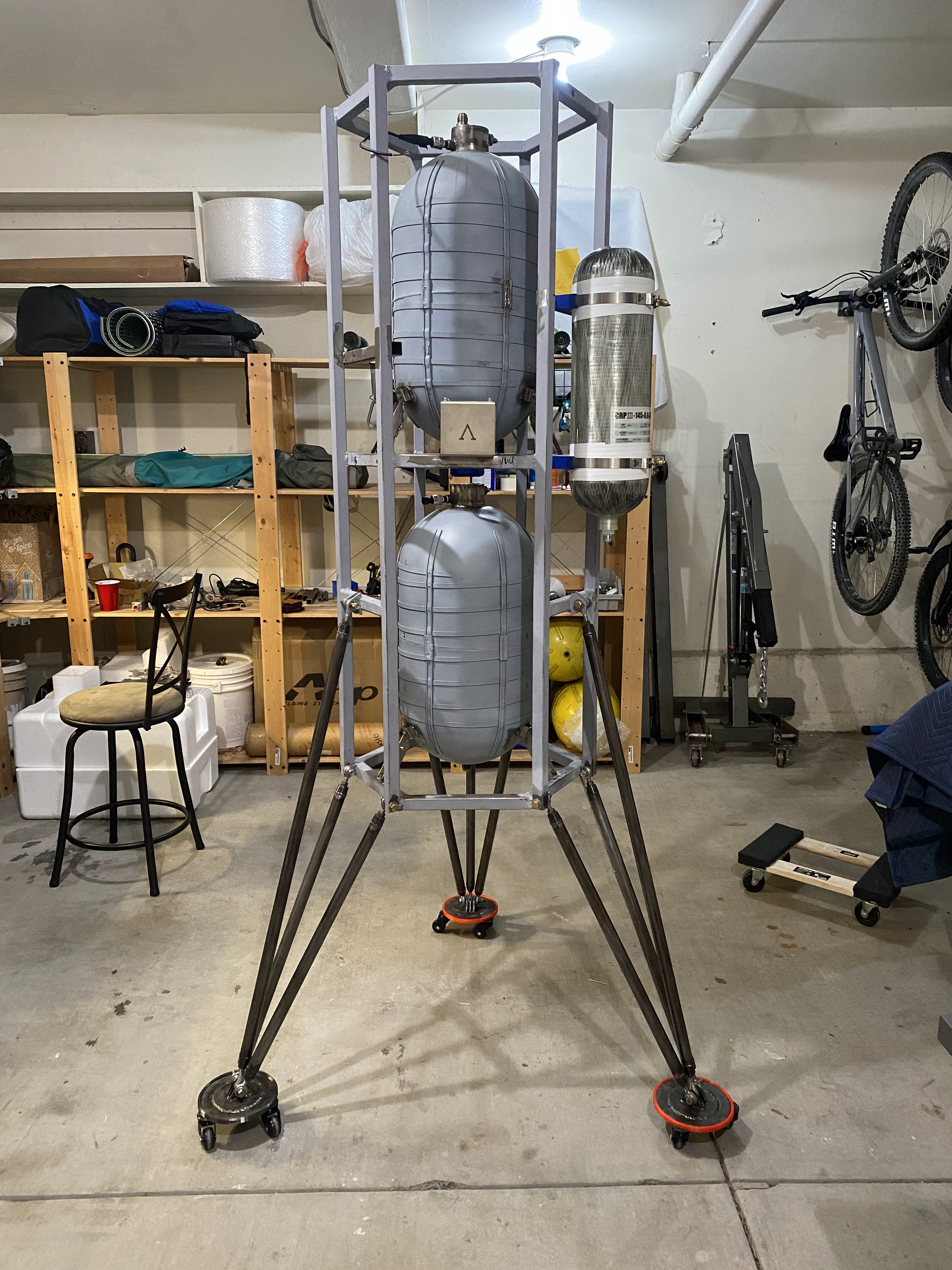
 It's been a bit since the last update. Damn. Guess that's how personal projects go when you are a real adult. That doesn't mean I haven't made progress! Here are a few pictures...


The Engine: Snort. It's been developed using this Master's Thesis https://ir.library.oregonstate.edu/concern/graduate_projects/76537857k and is in the public domain!


More information to come :) working hard to build and test and an engine this summer!
And I'm looking for sponsors! Please reach out on twitter 

Tuesday, February 21, 2023

Lander Update: Snort, the Engine

 So I've picked back up on liquid engine design for the lander. This is a brief of what I'm pursuing so far for the combustion chamber

Stats:

  • Thrust: 500lbf (2.22kN)
  • Pc: ~300 psi (2MPa)
  • Propellants: Liquid Oxygen, Ethanol 70%
  • Mixture Ratio: 1.35
  • 20% fuel boundary layer cooling
  • 15 degree conical half angle
  • L-star of 1 meter
  • 45 degree contraction angle on converging section, for manufacturability
  • Chamber Inner Diameter: 81mm
  • Materials: 304/316 Stainless Steel
I am first going to manufacture the chamber in two parts.. the cylindrical section, and then the printed or CNC'd converging-diverging section which I plan to weld on. The former is based on this affordable part from McMaster Carr. It's 304 stainless with a weld bead down the  center of it, and polished. I am a bit worried about the weld bead, but I know other chambers have been made similarly. The thickness is about 2mm, still checking to see if this checks out thermally. 

The ID of the chamber material is supposedly very accurate, so I've added a taper to the C-D section that traverses the inside the the tube, and can  be welded from the outside.

Here's Snort:


I've put out quotes for printing or CNC machining the C-D nozzle section and so far it only seems to be around $300 in stainless which is shocking to me.

If I can get each engine to be under $1k I'll be super happy. More to come on injector design and thermal analysis.. Need some friends to double check me :) Ideally, I'd like to print the injector and then weld it directly to the chamber, so I don't need to worry about fasteners, leaks, seals etc. Not sure if this is a good idea, but Armadillo had good luck with welding it all on there.


Tuesday, January 31, 2023

Lander Update - 01/2023 "We Have Lander At Home"

Long Time No Update. Each year I make it my resolution to be better at documenting my projects, taking pictures, and posting updates. This year my resolution is not only to be better at it, but to  finish the lander project (still unnamed, but dubbed Lander At Home memetically).

It's been a struggle to write updates in recent months, with life being so busy. But since I've last posted, a lot has happened. Since then I have welded the tank gas feed systems, hydro tested the tanks, and mounted them (no easy feat). I've came up with a COPV mounting system, and added one on. I've added a protective box for the IMU mount, with vibe isolation. I added in the cross brace for avionics box mounting. I added rollers to the lander, for easier transport and working. The TVC actuators have been trimmed down to size and tested with their ODrive board, but there are still some slight tolerance issues I'm working on that can be fixed with a shim or a re-machining some components.

The LOX tank mounts were designed to be 2D components, laser cut in 308 stainless from SendCutSend, and then fusion welded together. The bottoms are bent plate components that bolt down to the structure, with the structure being tapped itself. I did this so that the lox tank could be removable. But I mildly fu*ked up the alignment on two of them, and technically only need one to bolt down, so I am considering tacking the other two in place for flight. Not shown in the image below are the standoffs used to keep alignment correct.


I have designed and fabricated the engine gimbal thrust structure, but having some slight alignment issues. The center plate had a mild warping from tig welding (ugh) that I should have protected for, and the bottom  hex of the vehicle is ever so slightly offset that things don't line up perfectly. This, in theory, should be okay since the CG line is correct but the gimbal bias would be slightly zero seemingly (between thrust point and gimbal plate). It only looks a little hinky on close inspection.. I've designed adjustable bolt-on brackets that take up some slop translationally, but not torsionally. My friends say I should just accept it, and mount it, but I'm tempted to refab and make it perfect. Weeee shall seeeee. I need to stop getting lazy when I run into mild inconveniences.


Bottom of LOX tank, with fill/drain port capped off with a blue 10AN cap. Thrust structure assembly just being clipped in place here.

Here are a couple images from the LOX tank hydrostatic press test. The 4AN line is going off to a high pressure hand pump meant for air-rifles. The pressure transducer on the right is hooked up to a microcontroller and my laptop. I calibrated the ducer against atmosphere and assumed linearity, as the data sheet says.. The meter on the hand pump seemed like it read the same values. I went all the way up to 500psi, when I plan on using the tank at 300psi. No leaks, everything seemed to hold fine!


The gimbal plate itself is 6061-T6 aluminum that I had CNC'd by a separate shop. It only cost 40USD surprisingly, and met all my tolerance needs. It moves frictionlessly in 2 rotational degrees of freedom exactly as promised. Below are a couple more images of the gimbal plate and thrust structure. I am still considering a slight redesign for better rigidity in the backplate, and better mounting alignment. Over all these parts were perhaps 150USD, so not the end of the world. Peep the milled out NotForFlight tag on the gimbal plate.


I did a some work on designing the throttle valve. I had these ball valves laying around, and I know they each have some form of heritage in being used in other cryo liquid rocket projects. I think the Sharpe ball valve on the left has a hole cut in the ball to allow for slight venting of trapped gases, but I'm considering taking it apart and adding another. The linkage is finished, and there is minimal backlash in the assembly. The threaded rod will get cut and added to the end effector of the linear actuator.


The linear actuator for throttle valve. High bandwidth, and a cheaper variant of my TVC actuators. Still not my best work, but I need to finish things fast in order to break them.

I love heat threaded inserts. This was a PETG printed part that did not end up working out for me, due to being brittle and dimensions having shrunk too much for tolerance stackup of linear motion.

I made the brackets for my cheapo cold gas roll control thrusters, which are just solenoid valves with NPT to 4AN fittings, and tees. These will get plumbed to tank ullage/output of gas regulator at 300psi (at least for now unless I size something else).


TVC actuators...
I have been on a bit of an actuator crusade -- I am not happy with how I designed these. The non-stroke length fraction is too large, and these actuators really need to be much smaller than they are. But I need to move on to finish this project, so I need to make them work. Many months ago, I took some time to trim them down to size after the gimbal was designed, so I had a rough 20deg (overkill) tvc deflection in each axis. The actuator on the right is the trimmed down, the one on the left was my canvas, if you will.


I also took some time to tidy up the avionics box, wire up all the high current things, as well as update the firmware (video to be included). The image here is the relay board that turns on and off all the high current stuff. Again, probably should've added one more custom board to the design, and done this with solid state components, but whatever.. this has yet to be prove to me it won't work. It's also an order of magnitude cheaper, likely, than a custom job. Peep the high current amphenol connectors.


I ordered a chinese made ODrive 3.6 board (all the new ones stopped using USB and went full CAN), and it seems to work as intended so far!

The garage is back! It was previously occupied by an old roomates project car, which sort of spread all over. But now that it's vacant, the house can start to use it as a project shop. I have definitely been more productive and much happier with the free space so far.


That's all for now.. Once I finish throttle valve stuff, thrust structure/gimbal plate stuff, tank stuff, and firmware/avionics things (which are all in various completion states), I will move on to the high pressure system plumbing, propellant loading/unloading, and propulsion design. The goal for the majority of this year is propulsion design/fab/testing as well as flight software design/simulation/testing. I'd like the entire vehicle to be a flying wifi router, and have onboard HITL testing capability. The core GNC stack should not be terribly complicated for first test flights. There is much components testing to do, to understand throttle performance etc.

Here's a beautiful picture I took in Vancouver over New Years


Other things I should post

  • avionics box update
  • video of gimbals slewing
  • tank hystrostatic press tests
  • firmware stuff


Saturday, June 11, 2022

Lander Update - 06/2022

I have been doing a bad job of updating progress. I had intended on once per week initially, but life.

Lately I have been focusing on finishing up avionics and firmware, and getting moving on some of the other significant mechanical work I have head of me. I finished assembling the TVC actuators and have tested them. I also built up a portion of the ground station terminal I will be using to operate and work with the vehicle.

Current CAD state of the vehicle -- I have not worked on this portion much lately. I have recently determined how I plan on mounting the COPVs, although the CAD below is missing the bottom support bucket and strap. Those will be hose clamps seated onto a rubber or TPU cup. I also bought a TIG welder for the garage, so I can get cracking on work without having to visit the machine shop space.

All avionics boots up and works fairly well. Some weird bugs to fix in the peripheral board firmware. The backup IMU I got on ebay is behaving weirdly, and the analog multiplexer does not seem to be multiplexing as I expect. But I have reason to believe neither of these is a PCB issue, either device or firmware level. I'm able to drive all the relays, but there is a weird timing bug where when everything boots up, the relay board sinks power into the IO expander and fires itself for 250ms prior to Teensy poweron. Not really fixable via pullups, I'm going to take a closer look at the register map to see if there is a persistent fix. These annoyances always crop up lol. Parsing 2x GPS packets seems to work fine.


Linear Actuators! I've finally finished building them up, and testing out the drive board software. I had to update the firmware on  a linux system, so that required me using a raspberry pi, and I felt like I should just build a ground station computer while I'm at it. Anyway, the bandwidth already is quite good. I plan on  trimming the stroke once I have a design figured out for the thrust structure/gimbal plate and the mounting points for the engine/chassis side.


I also designed a smaller, cheaper, and hopefully more stable linear actuator that I might use for the throttle valve actuator. It uses a 22mm carbon tube as the effector. It also has some 3D printed parts that I'll need to sus out in PETG. Most other components are laser cut stainless steel. I still dislike the mounting situation..


Here is the prototypical grounds station in a pelican case. The portable monitor is used from ebay for $80 and is a super great deal. Basically an XPS15 screen you can just bolt down anywhere. I designed 3D printable adhesive bolt down brackets for it, with heat threaded inserts. Worked out quite well. The bottom of the case has a bunch of extra hardware you can tap into while out in the field. I will print some standoffs and laser cut an aluminum recess plate for the keyboard + other stuff to go onto. Work in progress!


I still need a good antenna solution...

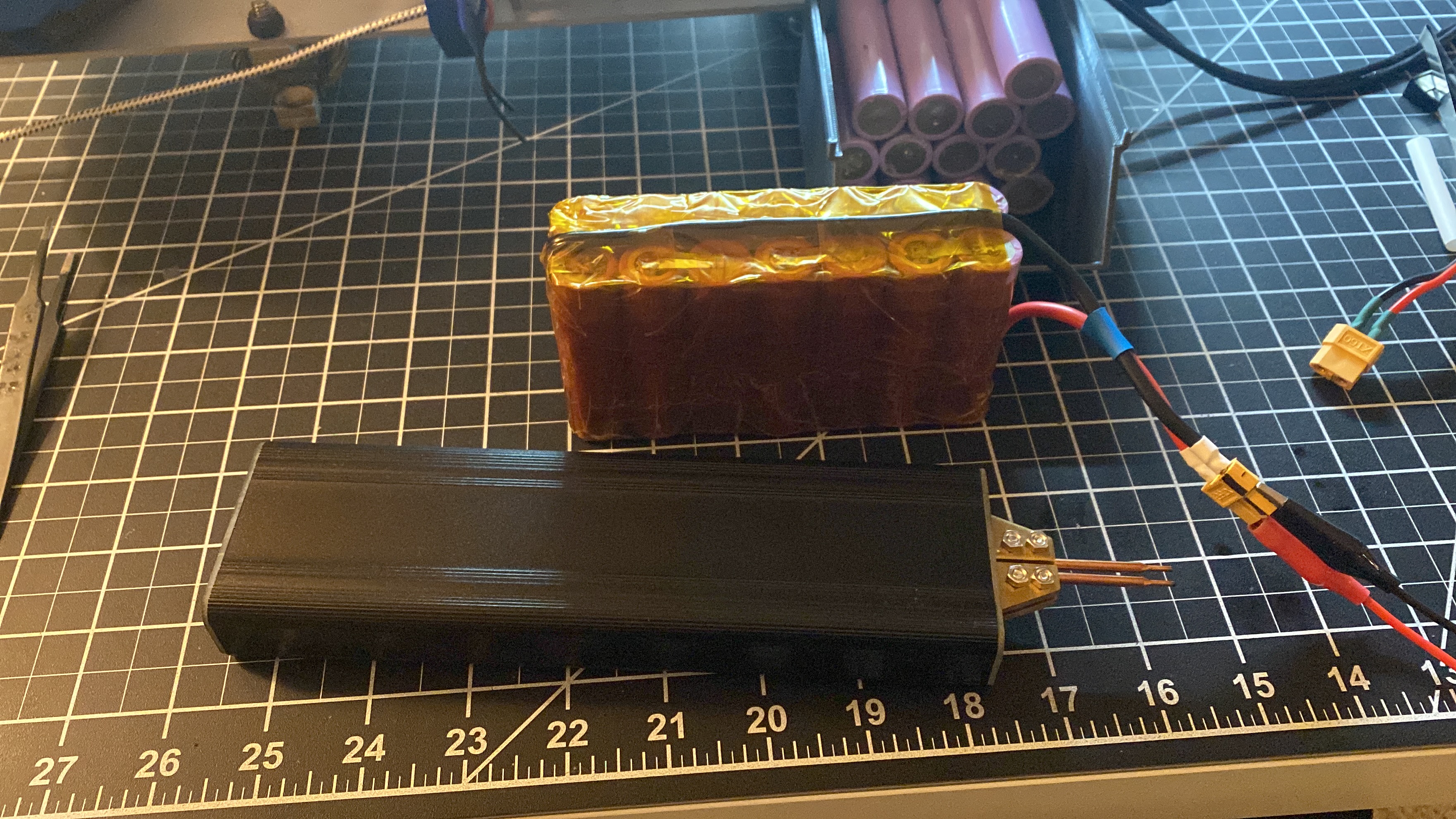
I also made some custom battery packs for the valve power supply. These will be dedicated to firing valves, and have all the right electrical isolation to separate systems.


The look sketchy, but I've done worse...

Still so much work to do.
  • Finish up small issues with avionics 
  • Get the ground station network piping figured out and update FSW, and start writing ground procedures for polarity testing.
  • Finish welding the feedheads and hydro test the tanks! Finally! Please!
  • Take what I learned and apply it to the lox tank, mount that to the airframe
  • Mount my COPV
  • Hold a design review w some of my friends for the P&ID plumbing diagrams for all fluid systems
    •  This will also help me figure out much more to spend on components.. I have most of the regs/valves and a bunch of fittings. but no tubing lol
  • Design and build the throttle valve
  • Finish thrust structure and gimbal plate design
  • FSW and GNC Sim work (Julia Lang?)
  • Engine design!!!!
  • Countless other things I have on my white board

Here's a great picture I took the other week.