
Long Time No Update. Each year I make it my resolution to be better at documenting my projects, taking pictures, and posting updates. This year my resolution is not only to be better at it, but to finish the lander project (still unnamed, but dubbed Lander At Home memetically).
It's been a struggle to write updates in recent months, with life being so busy. But since I've last posted, a lot has happened. Since then I have welded the tank gas feed systems, hydro tested the tanks, and mounted them (no easy feat). I've came up with a COPV mounting system, and added one on. I've added a protective box for the IMU mount, with vibe isolation. I added in the cross brace for avionics box mounting. I added rollers to the lander, for easier transport and working. The TVC actuators have been trimmed down to size and tested with their ODrive board, but there are still some slight tolerance issues I'm working on that can be fixed with a shim or a re-machining some components.
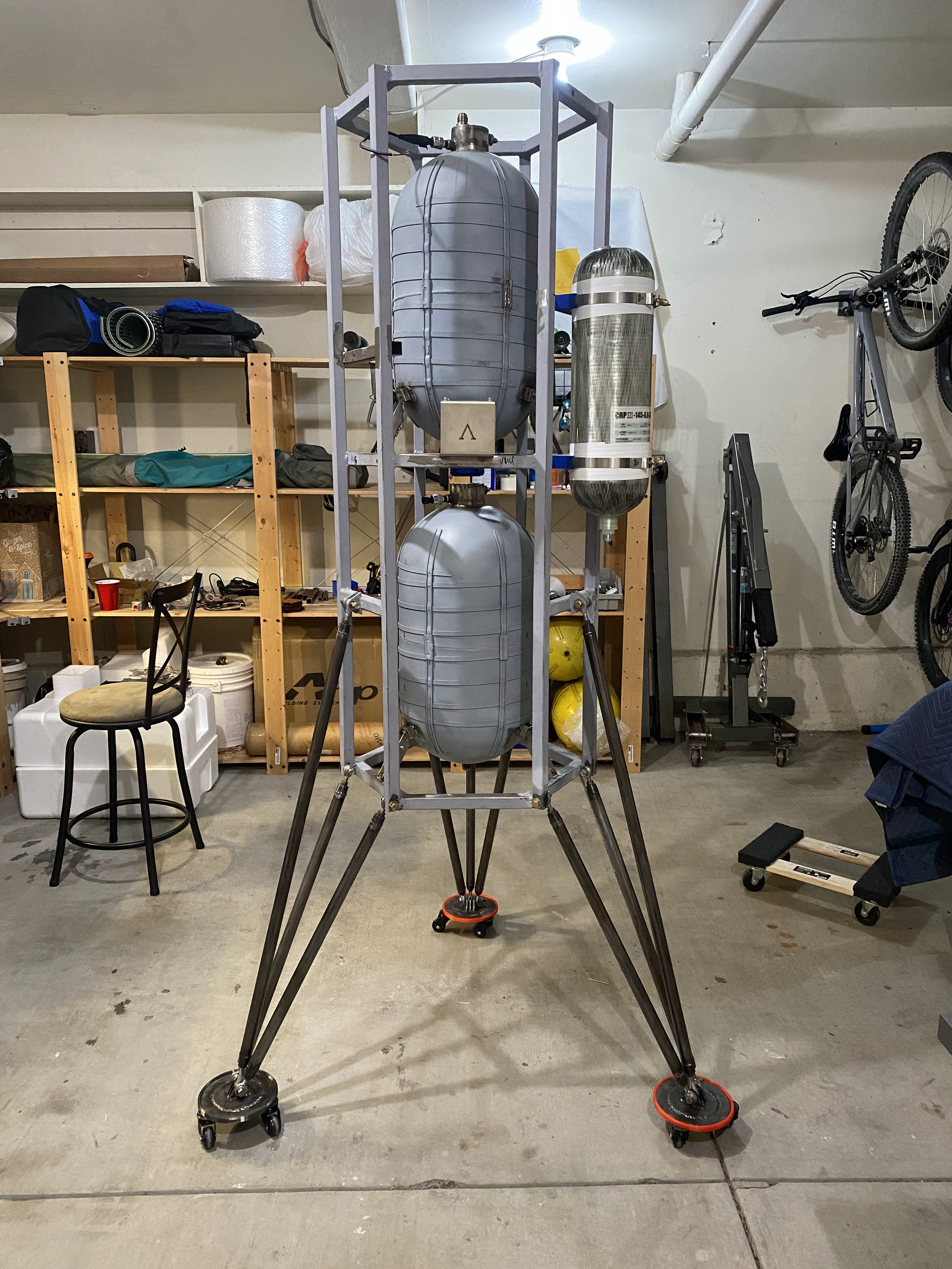
The LOX tank mounts were designed to be 2D components, laser cut in 308 stainless from SendCutSend, and then fusion welded together. The bottoms are bent plate components that bolt down to the structure, with the structure being tapped itself. I did this so that the lox tank could be removable. But I mildly fu*ked up the alignment on two of them, and technically only need one to bolt down, so I am considering tacking the other two in place for flight. Not shown in the image below are the standoffs used to keep alignment correct.

I have designed and fabricated the engine gimbal thrust structure, but having some slight alignment issues. The center plate had a mild warping from tig welding (ugh) that I should have protected for, and the bottom hex of the vehicle is ever so slightly offset that things don't line up perfectly. This, in theory, should be okay since the CG line is correct but the gimbal bias would be slightly zero seemingly (between thrust point and gimbal plate). It only looks a little hinky on close inspection.. I've designed adjustable bolt-on brackets that take up some slop translationally, but not torsionally. My friends say I should just accept it, and mount it, but I'm tempted to refab and make it perfect. Weeee shall seeeee. I need to stop getting lazy when I run into mild inconveniences.


Here are a couple images from the LOX tank hydrostatic press test. The 4AN line is going off to a high pressure hand pump meant for air-rifles. The pressure transducer on the right is hooked up to a microcontroller and my laptop. I calibrated the ducer against atmosphere and assumed linearity, as the data sheet says.. The meter on the hand pump seemed like it read the same values. I went all the way up to 500psi, when I plan on using the tank at 300psi. No leaks, everything seemed to hold fine!


The gimbal plate itself is 6061-T6 aluminum that I had CNC'd by a separate shop. It only cost 40USD surprisingly, and met all my tolerance needs. It moves frictionlessly in 2 rotational degrees of freedom exactly as promised. Below are a couple more images of the gimbal plate and thrust structure. I am still considering a slight redesign for better rigidity in the backplate, and better mounting alignment. Over all these parts were perhaps 150USD, so not the end of the world. Peep the milled out NotForFlight tag on the gimbal plate.


I did a some work on designing the throttle valve. I had these ball valves laying around, and I know they each have some form of heritage in being used in other cryo liquid rocket projects. I think the Sharpe ball valve on the left has a hole cut in the ball to allow for slight venting of trapped gases, but I'm considering taking it apart and adding another. The linkage is finished, and there is minimal backlash in the assembly. The threaded rod will get cut and added to the end effector of the linear actuator.


Other things I should post
- avionics box update
- video of gimbals slewing
- tank hystrostatic press tests
- firmware stuff
No comments:
Post a Comment