Sunday, December 12, 2021

A Garage, at last


I finally have space in my garage to start building, welding, machining. I'm hoping to make some quick progress as soon as craziness at work dies down a little.


Lander Updates: Avionics Bae

Some more progress on what I've dubbed the avionics bae of the lander. This houses the flight computer/connector board stack, power board, batteries, peripheral board, relay board, connectors, etc etc. I designed the divider panels to be 3d printed and have heat-sert threaded inserts. The metal parts were designed in CAD, laser cut, and bent using SendCutSend (excellent service, so affordable). The whole assembly is super rigid, and works well.  I added a PC fan for cooling, and the box is mounted using wire rope isolators for vibration isolation.


I also designed and printed  custom enclosure for the ODrive board, it also has everything secured with heat inserts, which work surprisingly well. This box will drive the brushless linear actuators I designed for the thrust vector control actuators. The USB cable was carefully picked for fit, and will get epoxied in place to make sure it does not back out. I wish I had a better solution, but that's the best I can do.
I tried unsoldering the screw terminal mounts, and even using my heat gun, but they're stubborn. I figured it'd be better for vibe just to solder to the pads. But so far I haven't been able to get a cable to back out by futzing around, so guess it might be okay. We will do more testing later.


Sunday, November 14, 2021

Lander Updates: Electronics box, Tank mounting, etc.

I haven't blogged in a hot second. My goal this year was to get something out once per month, so looks like I have a bit of a backlog at this point.

Since my past post: my car was totalled, moved all my stuff into a new house, and work has kicked back up. Recently, I have spent more time on the lander project, but not enough on parts that look... progressive. 

Also, if you are interested in supporting this project at all (be it component donation or whatever), feel free to shoot me an email at PSL58@ cornell.edu. I'm going to start looking for some sponsors, and will most certainly add a sticker panel to the side of the rocket listing all the awesome people that have helped me along the way. I'm 24, and just out of school, so little stuff goes a long way :) 

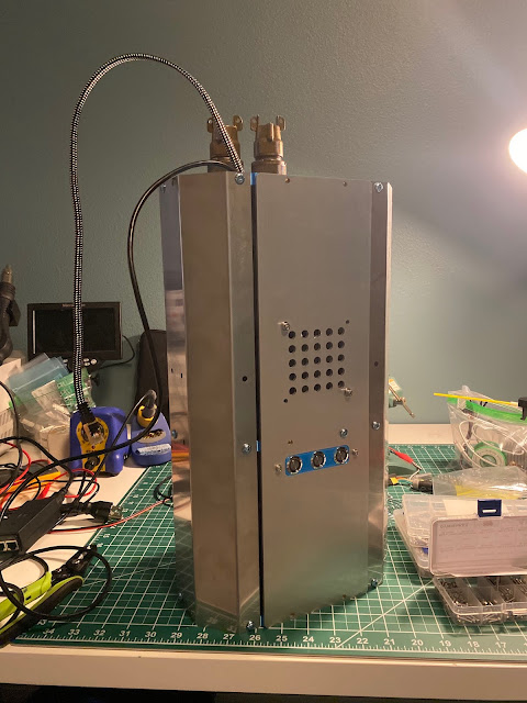
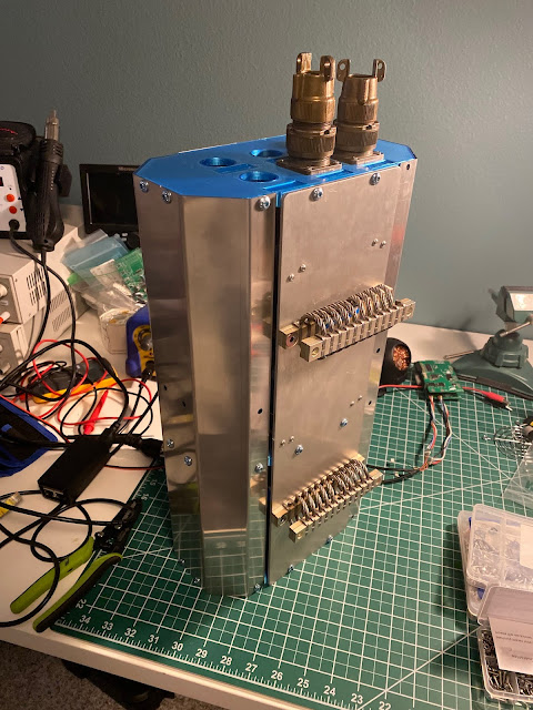
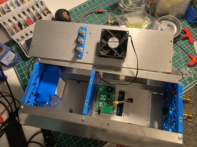
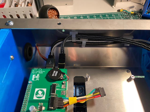
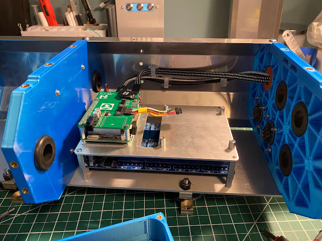
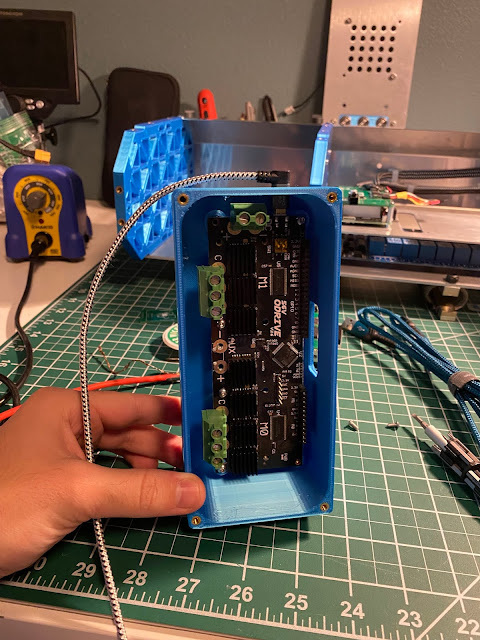
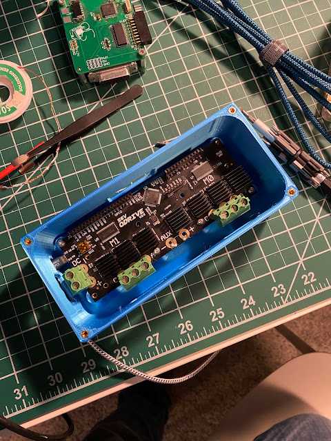
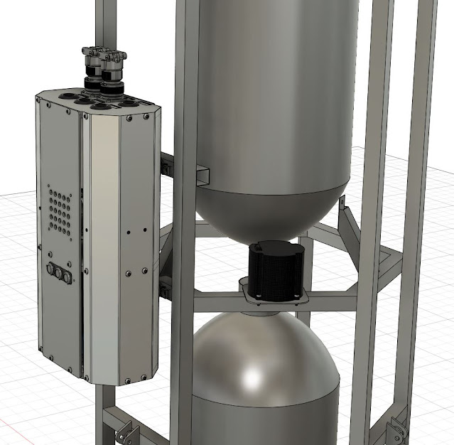
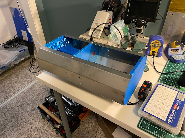
The avionics box is starting to take shape. For reference, this is what the CAD looks like. The CAD is missing a battery, two PCBs, and a couple other components.

Here you can also see a glimpse of the KVH1750 IMU that I am using (donated by my homie Adam Weld, thank you! could not afford this myself).

Here is some of the hardware coming together. The metal plates were laser cut by sendcutsend.com. Each of the divider plates is 3D printed with heat-serts (or whatever heated threaded inserts are called). The top plate, some avionics boards, and other components are still coming in.

You can see I have yet to print the connector end yet.
My lab also doubles as a guest bedroom, which explains the inflatable mattress lol.

I should have some more cool pictures of the electronics box coming soon, since there are a lot of parts on the way! I also will be finishing two more board designs soon. I scrapped my last board designs, because I realized I could abstract a lot of complexity by using USB devices and just using a Teenys 4.0 microcontroller rather than two STM32F4s with separate firmware and a silly dev environment.

Off in structures land, I have made some progress with tank mounting. I added the first tank and realized that what I had designed was certainly not rigid enough. I have since gone back to the drawing board.

The wobbly bastard


A close up of the tank welds I made.. They were to the external banding, and not the tank itself. I think I'm going to have to weld to the tank wall itself though on the new revision.
 

Also those bloody pins were tricky to bend into place.

Paddy's todo list for the rest of the 2021:
  • Power board finish
  • "Other Things" board finish
  • Tank mounts finish design, order parts, fabricate, mount tanks
  • Crane Mount design and fab
  • Pressurant tank mount design and fab
  • TVC actuators assemble, add in stop switches, make Odrive Enclosure, cut effector to size
  • Get all boards plugged together, powered, and doing things
  • Weld TVC mounts
Then 2022, I can focus on:
  • finishing my buddy's flight computer code (sorry for the latency on my end)
  • GNC / FSW and telemetry on the lander flight computer
  • Ground infrastructure --> cool pelican case typa dealio (I want to feel like I'm James Bond)
  • Propulsion work to the max
    • all plumbing, procurring rest of components
    • engine design, fabrication
    • thrust structure and gimbal

Saturday, July 31, 2021

Lander Legs

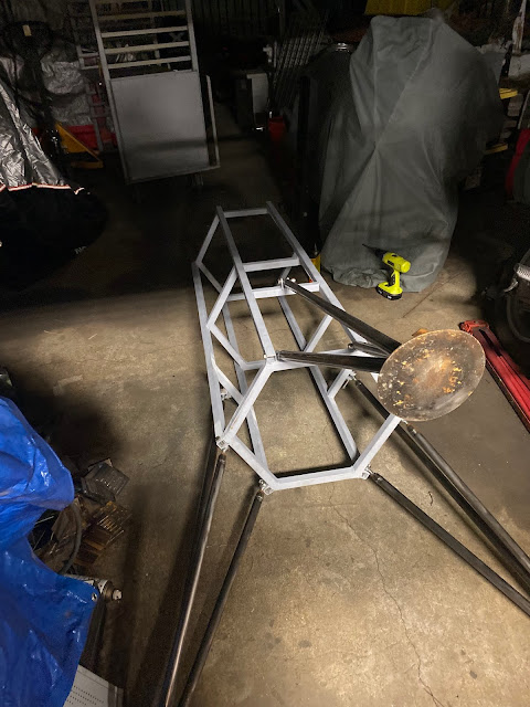
In designing the lander legs, I wanted them to be fairly modular and cheap in case I needed to change the design (stance and clearance) later to accommodate future design changes. I also wanted them to be pretty flexible to adjustments, generally. I decided to take this time to exercise sendcutsend.com for laser cutting steel parts, and also try my hand at some TIG welding. Each of the leg rods has a weld nut at the end, and each plate is laser cut and then welded together. These were some of my first welds, and they did not turn out too bad. I did have an issue with warping on the feet, as I did not provide enough heat sink material on the bottom and my weld current setting was a tad high.

Here are some pictures in no clear order of operations:


Notice the center rod uses clevises while the side rods use spherical rod ends.
The center bracket is ground down a little for the clevis to fit through. The look a little off center, but I promise that's just asymmetrical grinding :)


Without nuts on the rod ends:


The council of legs have spoken
honestly, a little proud of these, they look sick


I also fabricated the cross bar for the center rod and clevis to mount to. This was just a 1 inch steel tube with two brackets welded to hold the clevis in plate. I MIG welded this to the chassis at the correct height for the legs, and made sure each side was at the correct height. All the bolts are 3/8"-24. Also don't get any shavings into the threads and then tighten a nut over that -- good recipe for seizure and needed a cutoff wheel :). 

Oh man, and it looks super sick (first picture is through fish-eye):


A Paddy for scale...

Tuesday, July 27, 2021

Lander Airframe and Tank Work

I decided that 2021 will be the year I finish all the structural components, tank components, avionics, and linear actuators for the lander project. We'll see if that happens. This gives me time in 2021 to focus purely on GNC, software development, propulsion, and testing.

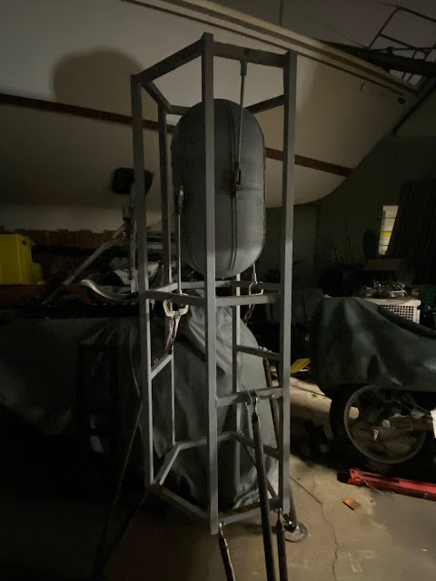
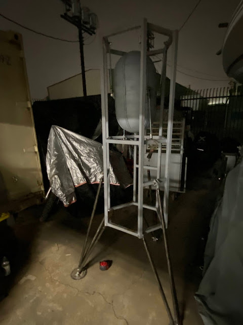
My friend Keith helped me out by fabricating the airframe. I did not have access to a welder at this point, so this was a major help. Here are a couple pictures from the process. You can see that he has two of the same types of tanks that I have/will be using. It was cool to get an initial perspective picture like this.

Here is the airframe in my living room after I primed it. You can see one of my fuel tanks in the center, as well as my pressure sphere off to the left. Nalgene for scale.


Here is the airframe with my two tanks laying there prepped and ready to go.


As far as the tanks go -- these are WWII Oxygen tanks from B24 bombers that were initially rated to 500psi. Here they are in their element:

My tanks were not as beautiful when they came in 


After sandblasting and priming:

There is still much work do be done on the tanks. Their feed system needs to be designed, fabricated, welded, and then pressure tested (I should not be using higher than 300psi). I should probably hire a professional welder for this, given how important consistency will be.

Another not-fully-filled-in CAD pick of what the vehicle should look like. Lots more to put into it.


Sunday, June 6, 2021

Considerations for Practical Problem Formulation

 When writing guidance algorithms or optimization routines (or reading papers about them), I tend to see best results come from asking these questions. Some of them are redundant, but can apply differently at different scales. 

  • How can I simplify the formulation?
  • Can I get away with a bad initial guess?
  • Can I abstract the complicated parts to a look up table and then run a simplified routine over this with a new initial condition?
  • What methods will provide a reliable and  efficient implementation?
  • Is the problem formulation dynamically feasible?
  • Can this be fast and or parallelizable? 
  • Can I separate the problem into disjoint components and solve for each part separately and or in a parallel fashion?
  • How do I take advantage of new frames or new mappings to construct a minimal dynamical representation?
  • How does this new problem scale? 
  • How does this problem linearize, how many orders must I include to provide an accurate representation of the nonlinear dynamics?
  • Are there ways to relax some constraints of the problem?
  • What methods will provide the fastest solution? Is it possible to pose the problem in that framework?

Wednesday, May 12, 2021

The Lander Project

 So... I have been working on this for a couple years now. I only really got the chance to go fast on it since I got my full time job one year ago (more time and money than school). It's been slow progress, since I really can only devote nights and weekends to it.

The goal of this project: produce a small rocket lander that is affordable to operate which provide 60 seconds of flight time, is reusable, and will allow me to fly new and interesting guidance, navigation, and control strategies. Do this as affordably as possible. Also just have a ton of fun and learn a bunch of things.

Since this started a while ago, this series of blogs will start off as a retrospective and move forward to the modern era (IE now). I have a couple names I am toying with: MiniLander or Hoplite. The former being somewhat self-explanatory; plus I have always loved the word Mini because it's cute. The latter is a play on words. It's a light hopper vehicle, but that word is also a Greek word meaning a citizen-soldier armed with a spear and shield. Plus I love historical shit. (ὁπλίτης) 

Here were the first couple parts I picked up for this project. I got a steel pressure sphere, electron beam welded, from eBay fo $50. Little did I know at the time that this was made by Fansteel for a Saturn launch vehicle... what a steal! I also got an LR101 engine from a friend. I wasn't sure I wanted to use it for this lander project, but I know I wanted to use it in the future and they are scarce. 


Here's the LR101 engine... It's a 1000lbf kerosene LOX vernier engine from an Atlas rocket form the 1960s. I won't use it for the lander... but probably a 10km vehicle or something :)


Here is the current cad of the system. You can see it's missing a lot of components, but good enough to size lots of my subsystems.


important disclaimer: don't try this at home kids. I mean really please don't try this at home, and in no way should you find yourself inspired to do so from this. This project has/will take me years, thousands of dollars, and is incredibly dangerous.

Keyboard Photo Dump

Here are various boards I have put together over the last couple years... I think I am pretty much done with mechanical keyboards for now, but may revisit in the future if I want to sell something. Onto other things.


And here is the last scratch built one I made, for my a friend